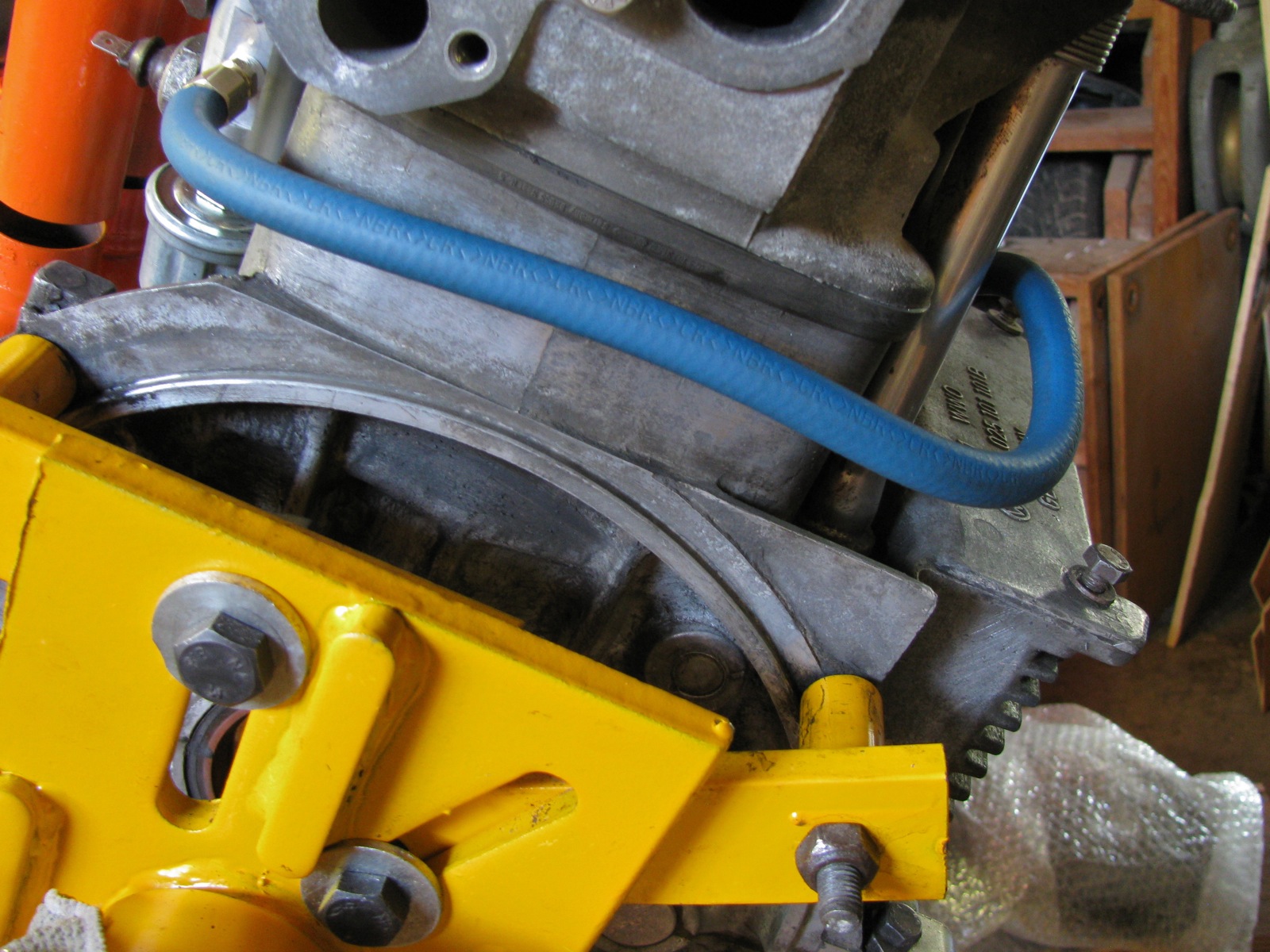
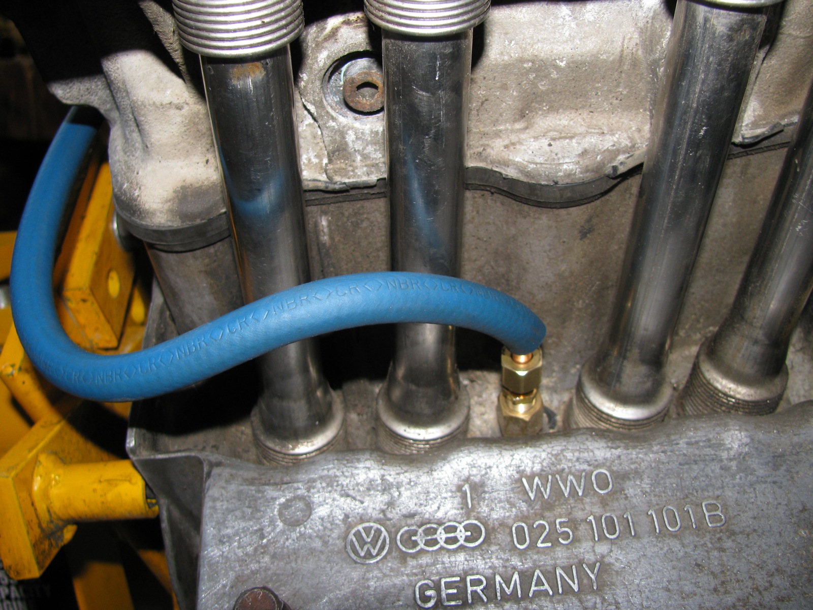
Been fooling around with relocating the high and low oil pressure switches so that I could add an oil pressure gauge sender and an oil temperature sender. There are commercially available kits to do this, but once again as I am cheap and keen to use the lathe, I made my own version (heavily influenced/inspired by Tencentlife’s work, shown here). A bit of aluminium rod, machined some flats and tapped some holes, some 1/4″ soft copper, compression fittings and a bit of fuel line to cover the copper. I used my spare motor to mock up install, probably needs more tweaking in the line, and will perhaps have to make a hole/slot in the rocker shield. Relocating the rearmost (is it the low pressure or high pressure? Can’t recall – ok, low pressure sender on left side, between pushrod tubes, high pressure sender on rear, below and to right of oil filter mount boss) sender frees up that spot for a temp sender.


Categories
- aircraft (48)
- around the airport (47)
- cyclekart (2)
- farmlife (34)
- greenwood canoe (2)
- metal working (18)
- metalworking (32)
- other (51)
- other cars (38)
- syncro (149)
- syncro specific repairs (76)
- tools (19)
- trips (47)
- Uncategorized (13)
- vanagon (476)
- vanagon engine swaps (4)
- vanagon mods (271)
- vanagon tech papers (24)
Blogroll
- Daswolgang – Andy's T3 Atlantic blog, good stuff here
- Ed's blog of his Syncro Westy major rebuild
- German tech. info site for T3 (vanagon)
- Herman's syncro project
- One Man's Spanner
- Samba forum for vanagons
- Slow car fast house Travels ALL over N. America
- Vanagon hacks and mods Great source of ideas for mods
- Vanagonlust Tumblr with good Vanagon pics
- Vanagony Just like it sounds
- Vw camper blog Abundance of vw camper info
- Wordless Me
- WordPress.com
Archives
- March 2024 (1)
- February 2024 (1)
- January 2024 (1)
- December 2023 (7)
- November 2023 (2)
- September 2023 (1)
- August 2023 (2)
- July 2023 (11)
- December 2022 (2)
- November 2022 (4)
- September 2022 (2)
- August 2022 (4)
- July 2022 (9)
- June 2022 (1)
- April 2022 (4)
- March 2022 (8)
- February 2022 (3)
- September 2021 (1)
- August 2021 (18)
- June 2021 (1)
- May 2021 (2)
- April 2020 (4)
- March 2020 (2)
- February 2020 (18)
- October 2017 (2)
- August 2017 (2)
- July 2017 (13)
- June 2017 (7)
- May 2017 (12)
- April 2017 (6)
- March 2017 (20)
- February 2017 (3)
- January 2017 (2)
- December 2016 (4)
- November 2016 (2)
- October 2016 (3)
- September 2016 (5)
- August 2016 (7)
- July 2016 (9)
- June 2016 (8)
- May 2016 (3)
- April 2016 (15)
- March 2016 (2)
- January 2016 (1)
- December 2015 (1)
- November 2015 (7)
- October 2015 (1)
- September 2015 (5)
- August 2015 (3)
- July 2015 (16)
- June 2015 (6)
- May 2015 (2)
- April 2015 (6)
- March 2015 (13)
- December 2014 (1)
- October 2014 (1)
- September 2014 (6)
- July 2014 (2)
- June 2014 (2)
- May 2014 (3)
- April 2014 (3)
- March 2014 (3)
- February 2014 (5)
- January 2014 (1)
- December 2013 (5)
- November 2013 (12)
- October 2013 (5)
- September 2013 (2)
- August 2013 (8)
- July 2013 (9)
- June 2013 (7)
- May 2013 (9)
- March 2013 (6)
- February 2013 (7)
- January 2013 (5)
- December 2012 (6)
- November 2012 (2)
- October 2012 (3)
- September 2012 (6)
- August 2012 (7)
- July 2012 (12)
- June 2012 (11)
- May 2012 (4)
- April 2012 (6)
- March 2012 (5)
- February 2012 (19)
- January 2012 (10)
- December 2011 (10)
- November 2011 (17)
- October 2011 (7)
- September 2011 (8)
- August 2011 (4)
- July 2011 (22)
- June 2011 (21)
- May 2011 (19)
- April 2011 (5)
- March 2011 (9)
- February 2011 (32)
- January 2011 (12)
- December 2010 (7)
- November 2010 (7)
- October 2010 (3)
- September 2010 (3)
- August 2010 (30)
- July 2010 (7)
- June 2010 (8)
- May 2010 (11)
- April 2010 (12)
- March 2010 (6)
- February 2010 (4)
- January 2010 (8)
- December 2009 (3)
- November 2009 (36)

#1 by Pz on July 5, 2012 - 7:57 pm
Wow, nice work Alistair…
Yes-on the rear-most as the low pressure sensor location…
It is….. rear-most and low-pressuret… AFAIK
The rear low-pressure location will work for a temperature sensor… Kinda…?
Heat-Soak from the engine block will raise the ambient oil temperature measurement some…
How much… I dunno? A couple of Sambista’s have guessed, perhaps plus 10 degrees Fº/Cº
At 10 degrees differential, who cares which dimension is utilized… 🙂
Not the triple point of water, I say…. 🙂
An alternative measurement location in within an oil hose or pipe.
At the out-put of an oil-cooler is one suggestion.
Anyway.. nice work…. thanks for posting…
Pz
#2 by albell on July 5, 2012 - 8:26 pm
Phil, the rear pressure sender location is right on an oil galley connected to oil filter. I would have thought it a good place, and what choices have I? Put it in the high press sender location? Then how to lead pipe for manifold, no room at rear, really, to bend the copper round.
ab
#3 by Peter Richardson on July 6, 2012 - 6:04 am
I like your work on this and all your other vanagon fixes. I was thinking about locating the manifold off of the engine in order to avoid vibration. Maybe on the Drivers side of the engine bay forward of the coil. What do you think?
#4 by albell on July 6, 2012 - 6:56 am
Hi Peter,
Thanks for the kind words. I wonder about mounting “manifold” on body. I think there would be more strain/stress on the extension line and fittings as the engine would be moving in relation to the body. Might not be an problem with a stainless flex line, but would not be great with the copper I used.
cheers
ab
#5 by Celeste on August 2, 2012 - 11:41 am
hey i visited the site…it is a nice site. thanks for providing information here…i like your blog post too thanks a lot.
#6 by Tony on March 12, 2013 - 7:05 am
So Alistar, I wanted to know how much length did you need for the copper pipe? Also since you did this have you had any issues with stress in the couplings? I found a grease gun hose with 1/8 npt at 18″ long that looks like it could do the job.
Thanks, Tony
#7 by albell on March 12, 2013 - 9:04 am
Tony,
I think 18″ of pipe will do it. I don’t have that engine rebuilt yet so the install has not been tested. The damn thing is still on the engine stand – I am the worse procrastinator.
alistair
#8 by Tony on March 12, 2013 - 9:38 am
Thanks for the input, Im building this from scratch. I found some neat manifolds at McMaster-Carrhttp://www.mcmaster.com/#additional-manifolds/=luixir
I keep reading that 1/8 and M10 treads are basically the same. 2 things come to mind with that information. 1) I can tread the hose directly to the case, 2) I could get an 90* or 45* adapter and tread it to the case and then the 1/8 case to that. My worry is flexing of the hose on to the fitting to the case. Any sage advice there. I was going to secure the apparatus to the engine.
#9 by albell on March 13, 2013 - 7:57 am
Tony,
If I recall correctly 1/8 npt and M10 are really close and only differ slightly in thread pitch. So they can be interchanged, some folk think it is ok, some folk think it is “not done” 🙂
I would look into the 90 or 45 to give you a nice lead out of the case.
Another worry raised by someone was that compression fittings can/might loosen over time. The suggestion was to use flare fittings (like brake lines). It is an option worth considering.
keep me posted on how things progress,
cheers
ab
#10 by Tony on March 13, 2013 - 8:32 am
I placed a comment in an existing tread in the samba. So far my numbers point to a cost of ~$26 US. That would include a possible 45*-90* adapter.
http://www.thesamba.com/vw/forum/viewtopic.php?t=508873&postdays=0&postorder=asc&start=20
We’ll see what turns up
Tony
#11 by Jake59 on May 7, 2013 - 9:39 pm
Nice blog, great photos and detailed information for us driveway mechancs. I had one question about locating the high pressure sender in this manifold. Are both current location directly connected?I having never split a water boxer block so I do not know for sure. However, this sure is an easier place for checking for their proper operation versus behide the water pump or under the cylinder heads.
Steve
#12 by albell on May 8, 2013 - 8:50 am
Hi,
sorry, I have no idea on how the oil galleries run. About the manifold – I’ll be getting back to this install fairly soon. I decided to take the heads off the spare motor (the one I mocked up the manifold on) and after doing a little work onthe heads, will be installing them into my current WBX. Current motor need the exhaust manifolds replaced, and it will mean pulling engine (bolts/studs badly rusted). I thought I might as well do some more work with engine out.
cheers
alistair